Posts

Showing posts from July, 2018

8MB setup for a Tandy CoCo3

Image
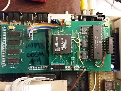
Years ago the NoCan series of add-on PCB's was developed. Now today with more resources available to use, the NoCan-8MB is back. The first go-around is a prototype unit only. Updated: Aug/30/2018 Here is a single picture of the current setup. Since the PCB layout limits the size of any PCB, it's in two pieces currently. A memory PCB (left PCB) and a DAT PCB. It started with the 2MB setup and received some hand-added wires to use up the rest of that 16 x 4 SRAM (74LS189). The 8-wire cable at the bottom of the DAT PCB (right PCB) is the JTAG connection. It was tested with Robert Gault's memory test software, originally designed strictly for the NoCan-8MB boards. Thanks Robert! I used the same memory PCB and stuffed another DAT PCB to test an 8MB CPLD. How to use the extra 6MB in a NoCan-8MB device. The following initializes a ramdisk already named "/r0" (/rzero),  and fills it with the contents of /DD/CMDS. <enter> Means

2MB Setup for a Tandy CoCo-3

Image
The 2MB system runs and NitrOS-9 6809E works. Pictured is a 6809E just for testing. This is a prototype just to see if the old CPLD code still works (from circa 1998 or so). Reminiscent of the older "NoCan" series of pcb's. This should be an exact copy of the NoCan8MB pcb, for software purposes. Features: Yellow LED to show 2mhz is on or off. Yellow LED to show power is on. Newer pcb will have an LED to show any 8MB activity, along with a jumper to allow or stop memory above 2MB. On the left pcb, 4 each 4m x 4 bit drams (8MB total). With a 8 pin connection to the DAT when desired. Without the DAT it's just 512K. On the right pcb is an isolated and buffered CPU  with a 2MB DAT (Lattice CPLD + 74LS189 sram). The 8 wire cable is for the extra address lines, etc. The two wire cable going south is for HSYNC and 28MHz from the GIME to keep all in sync. JTAG connector there too. The two wires on the right are mistakes and are not needed. Thanks